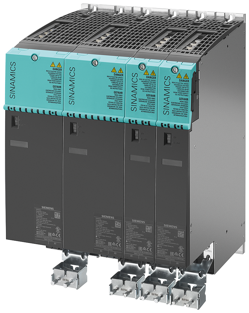
Overview
| Voltage and power ranges | 0.12 - 5,700 kW 1AC 230 V, 3AC 380 - 480 V and 3 AC 500 - 690 V (50/60 Hz) |
| Control principle: | V/f open-loop control, Vector control with/without Encoder, Servo control with/without encoder |
| Cooling: | air and liquid cooling |
Brochures
Videos
Downloads
FAQs
What safety category are the drive safety functions rated to?
SIL2, Cat.3/PL d
How can I test and document the safety configuration?
By using a a script, the Safety Acceptance Test and associated documents can be efficiently executed/recorded. The latest script is available at:
In an emergency stop state I disable my line module at the same time as the drives. Is this the best/safest way?
No. The line module should be disabled when all axes have stopped moving. This allows for the line module to regenerate any excess energy that is produced by the motors stopping. A typical example would be to use a delayed safety contact to disable the module after the SS1 delay time has expired.
What could be causing a return value of 8090 for DPRD_DAT/DPWR_DAT?
The hardware ID may be incorrect on the LADDR input. The required ID is the one used by the telegram - not the ID of the drive. For Startdrive, this can be found in the device view by going to Properties > General > Telegram configuration > [device name] > Start address. For drives not configured with Startdive, this can be found in the device view byhighlighting the row of the telemgra in Device overview, then navigate to Properties > General > Hardware identifier.
I have a flashing green COM light on my Control Unit. What does this mean?
Communication from a master device is partially or yet to be fully established. Therefore, cyclic communication is not possible.
How can I review the previous alarms that are not currently active on a drive?
Go to “Drive” -> ”Diagnostics” -> ”Alarms history”
How Do I Replace Motor Modules On My Siemens Sinamics S120?
Replacements with Same Article Number
Safety Active, p9909 = 1, Topology comparison High
Step 1 – Ensure that p9909 = 1, this causes the serial number and the hardware version of the new replaced component to be automatically transferred from the actual topology into the target topology and then saved in a non-volatile fashion.
Step 2 – Power down the drive, replace the motor module and power back on. (Ensure when replacing motor module that you allow 5 minutes for busbar discharge before removing)
Step 3 – F01641[2] should appear. This fault means that a power module has been replaced with the safety on. To clear fault either set p0977 = 1, or preform a copy Ram to Rom and acknowledge.
Safety Inactive, p9909 = 1, Topology Comparison High
Step 1 – Ensure that p9909 = 1, this causes the serial number and the hardware version of the new replaced component is automatically transferred from the actual topology into the target topology and then saved in a non-volatile fashion.
Step 2 – Power down the drive, replace the motor module and power back on. (Ensure when replacing motor module that you allow 5 minutes for busbar discharge before removing)
Safety Active, p9909 = 0, Topology comparison High
Step 1 – Ensure p9909 = 0 so that serial numbers and hardware versions are not automatically transferred.
Step 2 – Power down the drive, replace the motor module and power back on. (Ensure when replacing motor module that you allow 5 minutes for busbar discharge before removing)
Step 3 – A01425 should appear stating that the serial number of the motor module has changed. To clear this warning set p9905 = 1 (This preforms a serial number transfer).
Step 4 – F01641[2] should appear. This fault means that a power module has been replaced with the safety on. To clear fault either set p0977 = 1, or preform a copy Ram to Rom and acknowledge.
Safety Inactive, p9909 = 0, Topology Comparison High
Step 1 – Ensure p9909 = 0 so that serial numbers and hardware versions are not automatically transferred.
Step 2 – Power down the drive, replace the motor module and power back on. (Ensure when replacing motor module that you allow 5 minutes for busbar discharge before removing)
Step 3 – A Warning A01425 should appear stating that the serial number of the motor module has changed. To clear this warning set p9905 = 1.
Step 4 – p9905 is to transfer serial numbers, this will be stored in the Ram on the drive. To ensure no issues arise a RAM to Rom must be performed. To do this either set p0977 = 1, or preform a copy Ram to Rom in the project.
Safety Active, p9909 = 1, Topology Comparison Medium
Step 1 – Ensure p9909 = 1 the serial number and the hardware version of the new replaced component is automatically transferred from the actual topology into the target topology and then saved in a non-volatile fashion.
Step 2 – Power down the drive, replace the motor module and power back on. (Ensure when replacing motor module that you allow 5 minutes for busbar discharge before removing)


